
Instructions for assembling the Crosser Cargo electric tricycle
Universal manual for self-assembly of the Crosser Cargo electric tricycle (body with sides). The instruction is based on official technical documentation, as well as practical experience in collecting specialists


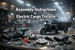
Complete Assembly Guide for the Crosser CARGO Electric Cargo Trike
Introduction
This guide is intended for self‑assembly of the Crosser Cargo (flatbed body) three‑wheeled electric scooter, 2025 model year. The instructions are based on the official technical documentation as well as practical assembly and operating experience. By following the recommendations provided, you will be able to install all components and systems to a high standard, ensuring reliable and safe operation of the trike.
The Crosser Cargo (flatbed body) is a rear‑wheel‑drive cargo electric trike designed to carry loads of up to 300–400 kg (depending on the variant). Thanks to its geared drive and powerful battery, the trike delivers excellent low‑speed traction and economy.
Main Technical Specifications
| Parameter | Value |
| Power circuit voltage | 60 V (DC) |
| Battery type and capacity | Gel, 5×12 V, 58 Ah (actual) |
| Motor rated power | 1200 W |
| Motor type | Brushed DC electric motor, geared |
| Tyre size | 4.00–12 (all wheels) |
| Drive | Rear‑wheel drive via gearbox |
| Brake system | Mechanical drum brakes on all wheels |
| Hand brake (parking) | Mechanical, acting on rear wheels |
| Suspension | Rear: leaf‑spring with shock absorbers; Front: telescopic fork |
| Lighting | High/low beam headlight, turn indicators, brake lights, side lights, reverse signal |
Package Contents
The factory packaging contains the following main assemblies and parts:
- Frame assembly with welded mounting brackets
- Rear axle (geared) assembly
- Electric motor with gearbox (pre‑assembled)
- Rear leaf springs (2 pcs) and shackles
- Rear shock absorbers (2 pcs)
- Rear wheels (2 pcs) with drum brakes
- Front telescopic fork (2 stanchions)
- Front wheel with drum brake
- Steering column with shaft and bearings
- Handlebar with control switches and wiring
- Body elements: cargo platform (tub), seat, rear sides, backrest, safety hoops, mat
- Battery pack (5 gel batteries)
- Motor controller with wiring set
- Brake cables, rods, pedals, levers
- Hardware kit (bolts, nuts, washers, split pins, cable ties)
- Tools (basic, for adjustment)
- Documentation (diagrams, data sheet)
Note: Due to shipping conditions (container transport), painted surfaces may show minor scratches and scuffs. This is not a defect and does not affect performance.
Safety Precautions
Before starting assembly, be sure to read the following safety rules:
- Work in a well‑ventilated area, preferably with a concrete or asphalt floor.
- Use proper hand tools. When working with electrical components, ensure tools have insulated handles.
- When lifting and tilting the frame, use an assistant – the weight of individual assemblies may exceed 50 kg.
- When handling gel batteries, avoid short‑circuiting the terminals. Do not drop batteries, as this may damage the case and cause electrolyte leaks.
- Make all electrical connections with the battery disconnected (circuit breaker in the OFF position).
- When tightening threaded connections in aluminium parts (gearbox, motor housing), take care not to strip the threads by applying excessive force.
- Use wooden or plastic drifts when pressing in bearings to avoid damaging the seating surfaces.
- Do not switch on the power until assembly is complete and all mechanical components have been checked.
Preparation for Assembly
1. Setting Up the Work Area
Choose a level surface of at least 3×4 metres. A workbench or sturdy stands for temporary placement of assemblies is desirable. Ensure good lighting. There should be nearby space for storing tools and fasteners.
2. Required Tools and Materials
Hand tools:
- Set of combination and ring spanners (8, 10, 12, 13, 14, 17, 19, 22 mm)
- Socket set with ratchet and extensions
- Screwdrivers: Phillips (PH2) and flat (5–6 mm)
- Combination pliers
- Side cutters
- Engineer’s hammer (500–800 g) with wooden or rubber face
- Pry bar (for levering rubber parts)
- Hex key set (for handlebar and control mounting)
Special equipment:
- Torque wrench (recommended for critical connections)
- Wooden drift or piece of hardwood for pressing bearings
- Heat gun (for warming rubber bushings and heat‑shrink tubing)
- Digital multimeter
- Continuity tester (buzzer)
Consumables (recommended to purchase separately):
- Anti‑corrosion underbody coating (stone chip) – 1–2 cans
- Paint matching the frame colour (for touching up scratches) – spray can
- Silicone lubricant (WD‑40 or equivalent) to ease assembly
- Heat‑shrink tubing (3–12 mm diameters)
- PVC insulation tape (black and red/blue for marking)
- Cable ties (200 mm and 300 mm) – at least 50 pcs
- Flat washers (M8, M10, M12) – stock of 20–30 each
- Spring (lock) washers for vibration‑loaded joints
- Stainless or hardened steel bolts (M8×25, M8×40, M10×30, M10×50) – assortment
Checking the hardware: before beginning, compare the contents with the parts list. If any bolts, nuts or washers are missing, buy them beforehand. Pay particular attention to the four long motor mounting bolts – they must have wide washers.
3. Unpacking and Inspection
- Carefully cut the packaging film without damaging the parts.
- Lay out all assemblies on a clean surface in the order of assembly.
- Perform a visual inspection:
- Frame: check for deformation or cracks in the welds.
- Body elements: ensure all sides, locks and hinges are present.
- Electrical components: check that wires are intact and insulation is undamaged.
- Batteries: measure the voltage of each unit (should be at least 12.4–12.6 V).
- Check completeness against the packing list.
4. Preliminary Treatment (Recommended)
- Anti‑corrosion treatment: turn the frame over and apply stone‑chip coating to the underside, especially around weld seams and suspension mounting points. This will protect against rust in service.
- Lubricating threads: apply a small amount of silicone lubricant to all threaded connections that will be tightened – this eases assembly and prevents seizing.
Step‑by‑Step Assembly
Stage 1. Preparing the Frame
- Place the frame on stands or turn it upside down (this makes it easier to install the rear suspension).
- Clean the mounting surfaces of any dirt.
- Touch up scratches if necessary.
Stage 2. Installing the Rear Suspension
2.1 Installing the Caprolon Bushings and Shackles
The rear suspension uses leaf springs with auxiliary shock absorbers. Correct installation of the shackles ensures proper suspension geometry and wheel travel.
- Bushings: insert the caprolon bushings into the front frame eyes (leaf‑spring attachment points). The bushings reduce friction and wear.
- Shackles: assemble the leaf‑spring shackles on a workbench. Each shackle consists of two plates joined by a bolt. Fit the shackles into the frame eyes, inserting the bolt with washers. Tighten the nuts, but not fully – final adjustment will be carried out after the springs are installed. Repeat on both sides.
2.2 Installing the Leaf Springs and Rear Axle
- Position the leaf springs on the frame support pads so that the spring centring pins engage the holes in the frame (usually on the underside).
- Place the rear axle on top of the springs. The axle has locating saddles that must sit squarely on the springs. Make sure the axle gearbox is oriented towards the front (facing the motor).
- Secure the axle with U‑bolts and clamping plates. The U‑bolts should wrap around the spring and the axle. Install washers and nuts.
- Tighten the U‑bolt nuts evenly in a cross‑pattern to a torque of about 40–50 N·m. Axle misalignment is not permissible.
2.3 Installing the Stabilizers (Control Rods)
The stabilizers (control rods) prevent lateral axle roll. Note that one rod has a left‑hand thread and the other a right‑hand thread. This allows length adjustment without twisting.
- Unscrew the stabilizers so that their length is equal on both sides. Rotate the central sleeve while holding the ends.
- Insert the stabilizer bolts into the corresponding lugs on the frame and axle. Use fitting washers.
- Tighten the connections. Then slightly loosen the rod mounts (if present) and achieve the minimum side‑to‑side axle movement (about 1–2 mm). Fully tighten all nuts.
2.4 Installing the Rear Shock Absorbers
- Extend the shock absorbers (remove any transport retainers first).
- Install the lower shock eye onto the axle bracket, inserting the bolt (with washers). Then attach the upper eye to the frame bracket.
- Important: the orientation of the shock does not matter, but make sure the rubber bushings are correctly installed.
- It is recommended to replace the original bolts with stronger ones (grade 8.8 or 10.9) and add washers. Tighten to a torque of 30–40 N·m.
Stage 3. Mounting the Electric Motor and Gearbox
The motor and gearbox are supplied separately but must be coupled. Some versions may arrive already connected – check your package.
- Remove the transport plug from the gearbox. Check the mating surface and seal – they must be clean.
- Carefully align the motor flange with the gearbox flange. Ensure the motor shaft splines engage with the gearbox. Do not use gaskets – the connection must be metal‑to‑metal.
- Insert the mounting bolts:
- One long bolt at the top
- One short bolt at the bottom
- Another long bolt and another short bolt – total 4 bolts.
- Critical: be sure to fit additional washers on the long bolts. This prevents pull‑out and ensures even clamping.
- Tighten the bolts evenly in a cross‑pattern to 15–20 N·m (sensitive, as the threads are in aluminium). Do not overtighten!
Stage 4. Installing the Rear Wiring Harness
The wiring harness running from the controller to the rear lights, brake lights and sensors is routed along the left side of the frame (as seen in the direction of travel).
- Locate the harness intended for the rear. It typically contains:
- Two white wires – for the rear brake lights (power).
- Red wires – power from the controller (sometimes with yellow terminals).
- Remaining wires – for the front (signal, control).
- Route the harness through the welded frame lugs (guides) so that the wires do not sag or contact moving parts.
- Secure the harness with rubber holders or cable ties. Do not over‑tighten the ties to avoid pinching the wires.
- Leave a length allowance for connecting to the lights and controller.
Stage 5. Installing the Brake System and Pedals
The trike is equipped with mechanical drum brakes on all three wheels. The system uses cable actuation with both foot and hand control.
5.1 Installing the Pedals
- The pedal assembly is located on the frame under the rider’s feet. Mount the pedals on the shaft: the left pedal has a lug for the front brake (to actuate the front wheel brake). The right pedal is for the rear brake.
- Secure the pedals using lock washers and locknuts. Make sure they rotate freely but without play.
5.2 Installing the Rods and Cables
- The short rod is for the front brake (runs forward). The two long rods are for the rear wheels.
- Connect the rods to the pedals and to the wheel brake mechanisms using clevis pins, washers, adjuster barrels and springs (return springs ensure brake release).
- Install the hand‑brake (parking brake) cable – it links the hand‑brake lever to an additional lever on the rear brake pedal assembly.
- Perform preliminary adjustment: by turning the adjuster barrels on the cables, achieve a setting where the brake shoes do not touch the drums when the pedals are fully released, and braking begins after the first 1/3 of pedal travel.
Tip: after final assembly and running‑in, a further adjustment will be needed.
Stage 6. Installing the Rear Wheels
- Turn the frame on its side (it is convenient to rest it on soft pads) for easier wheel installation.
- Fit the rear wheels (4.00‑12) onto the hubs. Make sure the hub splines align with the slots in the drum (if the wheels come with separate drums).
- Start the wheel nuts (usually 4–5 nuts per wheel). Do not tighten fully yet – centring adjustment will be required.
- Once both wheels are on, set the frame upright on the wheels and tighten the nuts in a cross‑pattern to 60–80 N·m (a torque wrench is recommended).
Stage 7. Assembling the Steering Column
Before installing the front fork, the steering column (head tube) must be assembled with its bearings.
- Press the two tapered bearings into the head tube: lower and upper. Use a wooden drift to avoid damaging the bearings. Make sure they seat evenly.
- Fit the steering shaft (which fits into the fork) with the cone facing downwards (towards the wheel). Insert it through the head tube.
- Slide the upper bearing onto the shaft, then the adjusting nut.
- Tighten the adjusting nut lightly to preload the bearings (they should settle). Check that the steering shaft rotates smoothly without binding and without noticeable play.
Stage 8. Installing the Front Fork
The front fork is telescopic, consisting of two stanchions, springs, triple clamps and mountings.
- Place the springs and washers onto the stanchions as shown in the diagram.
- Insert both stanchions into the head tube from below, securing them in the lower triple clamp (already fitted on the shaft).
- Mount the turn‑signal holders (rubber dampers) and the headlight on the upper part of the fork.
- Fit the upper triple clamp, securing it with nuts on the stanchions. Tighten the fasteners.
- Ensure the fork moves freely up and down and the springs function correctly.
Stage 9. Installing the Front Wheel and Fender
- Attach the front fender to the fork stanchions using 4 short bolts (usually supplied).
- Fit the front wheel with drum brake. Insert the axle, having first fitted the two spacer bushings (they ensure centring). It is recommended to add a 19×17 washer to compensate for any possible play.
- Tighten the axle nut and secure it with a split pin (must be fitted!).
- Install the front brake cable, connecting it to the lever on the wheel, and secure the guide (cable stop) on the fork.
Stage 10. Installing the Handlebars and Controls
The handlebars are mounted on the upper triple clamp. The handlebars carry the control switches, ignition switch, headlight, indicators and horn.
10.1 Mounting the Components
- Mount the horn on its bracket using two long bolts.
- Secure the headlight on the fork bracket. Connect the headlight wires according to the colour codes (see the “Diagrams” section).
- Fit the front indicators and the ignition switch in their designated locations.
- Fit the left and right control pods onto the handlebars. They are usually secured with Velcro straps (clamps) and self‑tapping screws.
10.2 Connecting the Wiring
Connect all the multi‑pin plugs following the colour coding. The main connections are:
- Left pod: blue plug (grey, black, white, violet, blue with white stripe); green‑red‑black plug (green, red, black); brake plug (black‑black, red‑red).
- Right pod: reverse signal plug, ignition switch, indicator relay (end plug).
- Headlight: black‑green (high beam), orange + blue (low beam), pink with white (mode switching).
Make sure all pins are firmly seated and free of oxidation.
Stage 11. Installing the Body and Parking Brake
11.1 Mounting the Cargo Platform
- Place the mat (rubber or plastic) into the platform, trimming to fit if necessary.
- Position the cargo tub (metal platform) on the frame so that the catch (latch) faces forward.
- Secure the platform with bolts (usually 4–6 points), using flat and spring washers.
11.2 Installing the Low‑Range Gear Switch
The gearbox has a lever for selecting modes (high/low range). Attach the knob or cable (depending on the variant). Usually a flexible cable with a clamp is used.
11.3 Installing the Parking Brake
- The parking brake lever is mounted on the left, under the seat. Fit the lever onto its bracket.
- Connect the parking brake cable, having first inserted it into its sheath and secured the boot.
- Caution: the parking brake spring is very strong; work carefully and use a lever to compress it.
- Adjust the cable tension so that the rear wheels lock when the parking brake is applied.
Stage 12. Installing the Controller and Electrical Wiring
The controller is the “brain” of the electric trike. It manages the motor, receiving signals from the throttle, sensors and controls.
12.1 Mounting the Controller
- The controller is usually supplied in a protective metal case. Fasten it to the frame near the battery compartment (often under the seat or at the rear).
- Use self‑drilling screws (for metal) or bolt it on. Ensure ventilation – the controller gets hot.
12.2 Connecting the Power Circuits
- Motor phases: connect the wires of the same colour: yellow‑yellow, blue‑blue, green‑green.
- Hall sensors: connect the plug from the motor to the controller (usually a 5‑pin connector).
- Controller power supply: use heavy‑gauge wires (red – positive, black – negative). Connect:
- Controller + terminal to the central wiring + and battery +.
- Controller – terminal to the central wiring – and battery –.
- Circuit breaker: install it in the positive wire (as close to the battery as possible) for overload protection.
12.3 Connecting Additional Devices
- Rear lights: connect the white wires to the brake lights (+12 V from controller, and ground).
- Reverse relay: connect the orange plug and two additional plugs according to the marking (usually a buzzer and a warning light are connected for reverse).
- Charging socket: connect it directly to the battery terminals (positive and negative) using wires of sufficient cross‑section.
Important: all connections must be properly insulated (heat‑shrink or insulation tape). Do not leave any bare sections.
Stage 13. Installing the Battery Pack
The batteries are gel type, 5 units of 12 V, connected in series to give 60 V. The total capacity is 58 Ah.
13.1 Battery Connection Diagram
text
+ BAT1 → – BAT2
+ BAT2 → – BAT3
+ BAT3 → – BAT4
+ BAT4 → – BAT5
The outermost positive (BAT1) and negative (BAT5) are connected to the system.
Procedure:
- Place the batteries in the compartment, securing them with the factory‑supplied clamps to prevent movement while riding.
- Connect them in series using the supplied jumpers. Use nuts with washers; tighten firmly.
- Connect the outer terminals to the controller and central wiring (positive via the circuit breaker, negative directly).
Check: before switching on the circuit breaker, measure the voltage across the outer terminals with a multimeter – it should read 60–65 V (depending on state of charge).
Stage 14. Final Body Assembly
- Install the rear safety hoop (2 long bolts at the sides + 1 bolt at the bottom). Tighten.
- Secure the seat: usually it hinges at two points at the front and a central bolt at the rear.
- Fit the rear sides and backrest of the body, using clevis pins, rubber straps and locks. Check that all fasteners work.
- Secure all wiring with cable ties under the body so that it does not hang down or touch hot parts (gearbox, motor).
- Mount the charging socket in a convenient location (e.g., on the side panel of the platform) and connect it to the battery.
Stage 15. Pre‑Start System Checks
Before switching on the power for the first time, carry out a thorough check:
- Mechanical part:
- All bolted connections are tight.
- Wheels spin freely; brakes do not bind.
- Steering is light, without sticking.
- Suspension works, with no abnormal knocking.
- Electrical part:
- All connectors are properly inserted; contacts are secure.
- Circuit breaker is OFF.
- There are no bare wires that could short to the frame.
- Batteries are fastened and polarity is correct.
- Functional checks (with the circuit breaker OFF):
- Turn the ignition switch on – the display (if fitted) should show voltage (without starting).
- Check the operation of the brake lights, indicators, horn and headlight (by temporarily feeding power from the battery via test leads, or by briefly switching the circuit breaker on).
Stage 16. First Start‑Up and Running‑In
- Apply the parking brake firmly.
- Switch the circuit breaker ON.
- Sit on the seat and make sure the throttle is in the zero position.
- Turn on the ignition. The indicators on the display should light up.
- Slowly turn the throttle – the motor should start smoothly and the trike should begin to move. Be prepared for a possibly abrupt start due to high torque.
- Check reverse gear operation (switch).
- Check gearbox shifting (low/high range) – it should engage cleanly, without grinding.
- Perform a test ride at low speed in a safe area, checking:
- Braking effectiveness (pedal and hand brake).
- Handling and absence of vibration.
- Operation of all lights.
- Motor and controller temperature (should not exceed 60–70°C after 5–10 minutes of riding).
Stage 17. Running‑In and After‑Sales Maintenance
The first 100–200 km are the running‑in period. During this time:
- Avoid prolonged full‑throttle operation.
- Regularly check the tightness of all bolts, especially:
- Axle U‑bolts
- Motor and gearbox mounts
- Wheel nuts
- Brake rods and cables
- After 50–100 km, perform a full re‑tightening of all threaded connections.
- Check the steering column bearings and adjust if necessary.
Additional Upgrade Recommendations
To improve reliability and service life, the following improvements are recommended:
- Replace hardware: replace the standard bolts (especially critical ones) with high‑strength (class 10.9) or stainless steel ones. Add washers wherever play exists.
- Anti‑corrosion treatment: additionally treat all weld seams, the underside and inside the frame with anti‑corrosion compound. Apply stone‑chip coating to the lower body parts.
- Seal the wiring: seal all points where wires enter housings (controller, connectors) with silicone sealant to protect against moisture.
- Additional lighting: if desired, add LED strips for cargo platform illumination.
- Strengthen battery mounting: provide extra restraint to prevent the batteries shifting during hard braking.
Wiring Diagrams (Detailed)
1. Electric Motor Connection
| Motor wire colour | Controller wire colour |
| Yellow | Yellow |
| Blue | Blue |
| Green | Green |
Hall sensors: 5‑pin connector (red – +5V, black – GND, blue, green, yellow – signals).
2. Controller and Battery Power Supply
- +60 V: from battery positive terminal → circuit breaker → controller (thick red wire) + central wiring (red).
- –60 V: from battery negative terminal → controller (thick black wire) + central wiring (black).
3. Control Panel Connectors
Left Panel (Lights, Indicators)
- Blue plug:
- Grey + black – left indicator power
- White + black – right indicator
- Violet + blue with white stripe – hazard warning lights (if fitted)
- Green‑red‑black plug: green (side lights), red (brake light), black (ground).
- Brake plug: black‑black, red‑red (signal to controller).
Right Panel
- Reverse signal button – connects to the controller.
- Ignition switch – breaks the controller power circuit (usually red wire).
- Indicator relay – end plug (connects to the left panel and indicator wires).
4. Rear Wiring
- White wires (2 pcs) – brake lights (+12 V from controller). Ground through the frame or a separate black wire.
- Red wires – rear light power (side lights).
- Orange + two plugs – reverse relay with buzzer. One plug goes to the reverse sensor, the other to the warning light.
5. Low‑Range Gear Switch
A plug with green, red and black wires connects to the switch on the handlebar (or a separate toggle switch). The signal goes to the controller to limit speed and increase torque.
6. Charging Socket
Connected directly to the battery (positive and negative) via wires of at least 4 mm² cross‑section. It is recommended to use a socket with reverse‑polarity protection.
Final Inspection Checklist
Before riding on public roads, ensure the following:
- All bolted joints are tight (especially wheel nuts, axle U‑bolts, motor mount).
- The brake system is adjusted: the foot brake locks the wheels when fully pressed, and the parking brake holds the trike on a slope.
- The handlebars turn freely, and the steering column has no play.
- All lights are working: headlight (low/high beam), indicators, brake lights, side lights, reverse signal.
- The horn sounds.
- The display (if fitted) shows voltage, speed, mode.
- The throttle controls the motor smoothly without jerking.
- Gear shifting is clean and quiet.
- Reverse gear engages and works.
- The circuit breaker is easily accessible and cuts the power.
- Batteries are secured, terminals tight and free of sparking.
- Wiring is fixed with ties, does not touch moving parts or rub through.
Possible Faults and Troubleshooting
| Problem | Possible cause | Solution |
| Motor does not start | Circuit breaker off; discharged batteries; faulty ignition switch; broken throttle control wire | Check voltage at controller; switch on breaker; charge battery; check ignition and throttle circuits |
| Motor runs jerkily | Poor contact in Hall sensor connectors; low voltage | Check connectors; measure battery voltage under load |
| Weak brakes | Cables out of adjustment; worn shoes | Adjust cables; replace shoes |
| Knocking in the suspension | Loose spring or shock absorber nuts | Tighten fasteners |
| Headlight not working | Bulb blown; corrosion in the connector | Replace bulb; check contacts |
| Noisy gear shifting | Gear not fully engaged; low oil level | Adjust shift cable; check oil level |
Conclusion
Congratulations! You have successfully assembled the Crosser Cargo (flatbed body) electric cargo trike. By following all the assembly and subsequent maintenance recommendations, the vehicle will serve for many years, providing reliable and economical cargo transport.
Remember:
- Perform regular maintenance every 1000 km: lubricate bearings, check tightness, brake condition and electrical equipment.
- Use only the recommended types of batteries and chargers.
- Avoid prolonged riding with a fully discharged battery – this shortens the battery life.
- In winter, store the trike in a warm place, recharging the battery periodically.
If you have any questions or difficulties, contact an official dealer or a qualified specialist.
Ride safely!

Recommended Products and Services


Related Articles
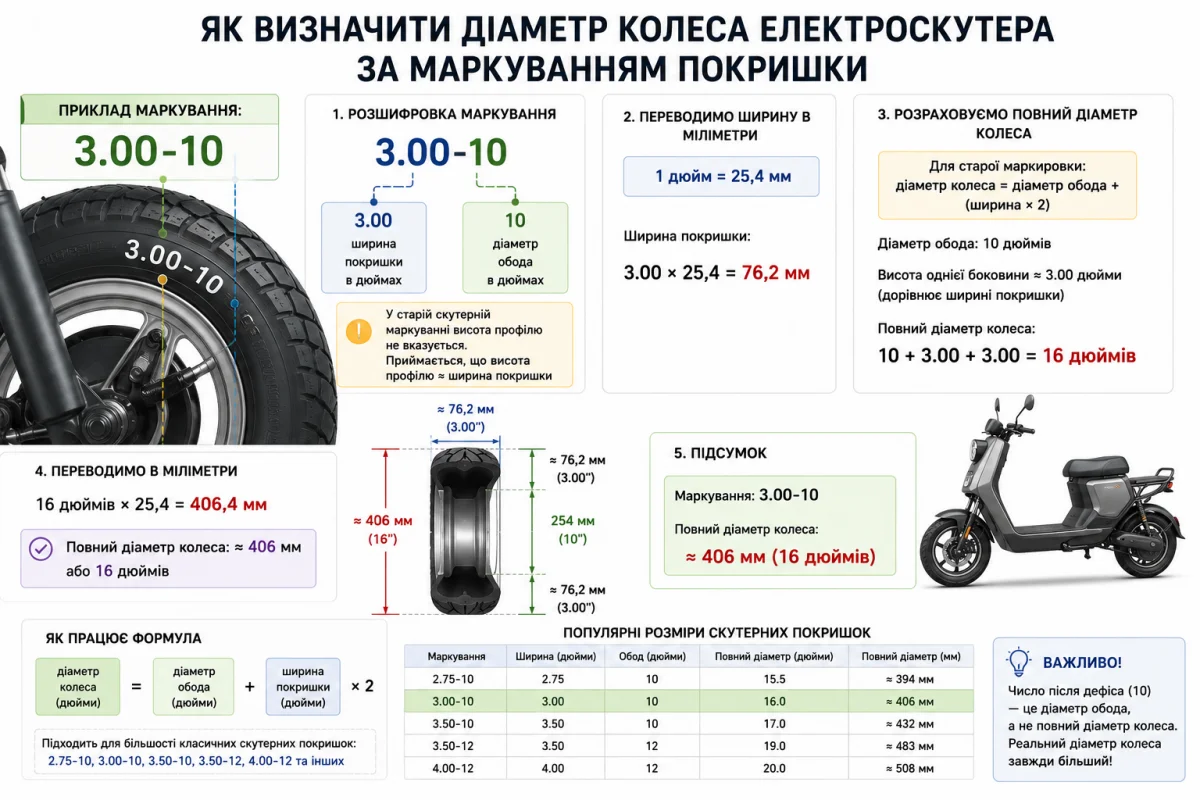
Як визначити діаметр колеса електроскутера
Як визначити діаметр колеса електроскутера за маркуванням покришкиБагато власників електроскутерів

Керівництво з обслуговування електроскутера (електромопед, електромоторолер)
1. ВступЕлектроскутер (електромопед, електромоторолер) — це індивідуальний транспортний засіб,

Де продати електроскутер або запчастини до нього в Україні
ЗмістДе продати електроскутер або розмістити оголошення про купівлю, продаж, обмін чи орендуКоли

